Small offgrid DC-first solar power plant - 2026 upgrades
Initial setup described here (2024)
Goals haven't really changed - with a still modest output I would like to consume as much power as possible as efficiently as possible. Especially when production is low around the winter season.
Taking my recent usage into account (around 1800kWh per year) I expect to be completely self-sufficient at least during the 8 most sunny months in the year.
When underproducing, any missing power is to be taken from the grid without any human intervention.
Some power needs to always be present in the system to serve as an UPS backup.
The box
I packed all the small pieces into an ELEGANT RN 3X12 MULTIMEDIA IP40 part number 2445-21 (elektro-plast.com.pl) enclosure (dimensions: 310 x 475 x 104 mm).
You can find those on ebay.
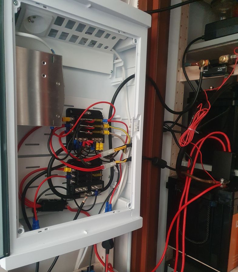
It comes with metal base plates that I drilled and used M3 rivnuts to mount my fuseboxes and the MIDIVAL fuse holder.
I drilled round holes for my cigarette lighter sockets and some additional ones for cabling. I keep the solar chargers outside of the box.
External power supplies for DC redundancy
I use two 4pin miniDIN -> miniFIT-JR adapters (minipc.de) for power supply connections.
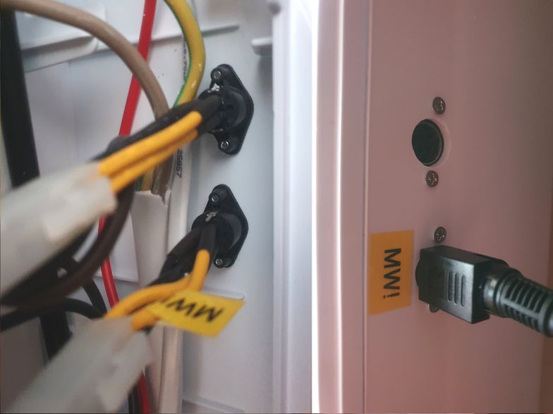
These are not excactly "4-pin mini-din jacks", they are Kycon KPPX/KPJX connectors (kycon.com).
Beware when using something like Mean Well GST120A/GST220A -R7B power adaptors, the pinout is different! I just swapped the pins of the MiniFit JR side of the adapter to match my setup (the one marked "MW!").
Kycon connectors provide more current carying capacity than barrel jacks (7.5A times two pairs), even more powerful power supplies from Mean Well come with 6-pin MiniFit JR connectors.
I drilled 12mm holes in my box with a step bit and than wiggled a little bit more to make the holes larger for the plugs to fit while still keeping it tight. Drilled 2mm holes for screws through the sockets to align, and 3mm afterwards. Secured the sockets with ordinary 10xM2.5 screws. That resulted in an excellent fit, tapped the plastic and doesn't require any nuts.
Y-PWR replaced with "redundancy blades" :D
I didn't like the Y-PWR (both in terms of price and performance) and been considering to design a custom PCB with LM74700 ideal diode controllers (or something similar) for a while now. In the meantime, I found out these common PCBs having decent transistors and at the same time the size and layout matching ATC/ATO fuses.
The ones I got from Aliexpress seem to contain the original TI chip. Not even the cheaper AP74700 from Diodes, Inc., that I normally use.
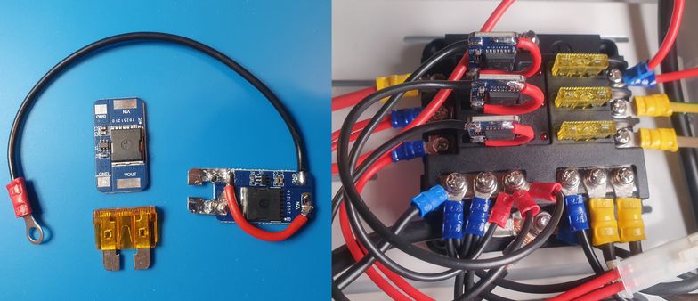
So, I did a few 5-minute hack jobs, sacrificed some fuses and ended up with "redundancy blades".
If you were to repeat my endeavor, be careful to cut away the track for VIN from GND close to the pad before the vias reaching to the bottom side. And it is easier to solder both legs with the help of some fuse holder keeping them properly aligned. The red current-carying wire is 2.5mm2 (14 AWG), the black ground is 1mm2 but 0.5mm2 or even thinner would be fine.
These will carry 25A of current each no sweat. Y-PWR will not sustain 10A + 10A without additional heat management. Power losses are also much much lower and everything runs much cooler.
You can have as many inputs as you want as long as your fuse boxes provide enough circuits. It is even possible to use multiple in parallel from the same power source - the load will be shared equally between them (same 20mV regulation of transistor voltage drop and identical transistors).
So, more power, less losses, less money and as many power inputs your heart will desire. :-)
24V upgrade, storage capacity x2
After some hesitation I decided to add a second battery and both increase the system voltage to 24V (20..28.4V actual) and storage capacity to about 5kWh.
Reasoning in favour:
- less cabling losses and I can still use my USB-PD accesories (car chargers work with both 12 & 24V)
- now I can use my 35A charger for 2 panels instead of 1
- two batteries will double system storage capacity
- I seem to have some hefty 24V power supplies for redundancy
- OpenUPS on the server is 24V-compatible
- will be able to use the XYZSTUDIO ZC858/ZC925 135W USB-PD step-down only port to power Lenovo laptops with 20V @135W.
Against:
- 12V to 230V inverter not compatible and need to buy a new one
- 12V to 48V DC/DC not compatible (need to buy one anyways)
- 24V inverters less common and typical integerated hybrid/off-grid inverters for solar are 48V
- battery expensive (but still, you get more capacity)
- two batteries in sesies, especially one new and one old, could lead to imbalance
- now I can't use my 12V-only fridge. :(
I managed to buy a Mean Well DDR-120B-48 DC/DC converter for PoE for ~half the MSRP price.
Managed to "trade-in" my slightly used battery and started with two brand new ones.
1 + 3 panels using 2 chargers
I added 3 additional JA Solar JAM60S20-385/MR 385W solar panels for a total of 4 (1.540KWp).
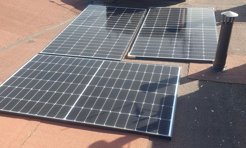
After some thinking and looking up the charger prices I decided to just buy a second Victron SmartSolar MPPT 150/35 MPPT charger and connect each one of them to 2 panels in series.
Reasoning:
- a Victron 150/70 (2 parallel 2 serial panel setup) is more then twice as expensive as two 150/35 chargers
- a Victron 250/70 (for all 4 panels in series) is almost 3 times more expensive in comparison to 2x 150/35
- I already have one 150/35 and currently don't have any other use for it
- a 100V max system (typically about 70V) operates almost at oficially safe DC voltage levels.
Against:
- I need a second cable set
- The smaller 150/35 doesn't have the fancy LCD screen option which I like.
Charge traction batteries or something else
I wired one of the chargers to the batteries through a Hager SFT140 change-over switch. (hager.com)
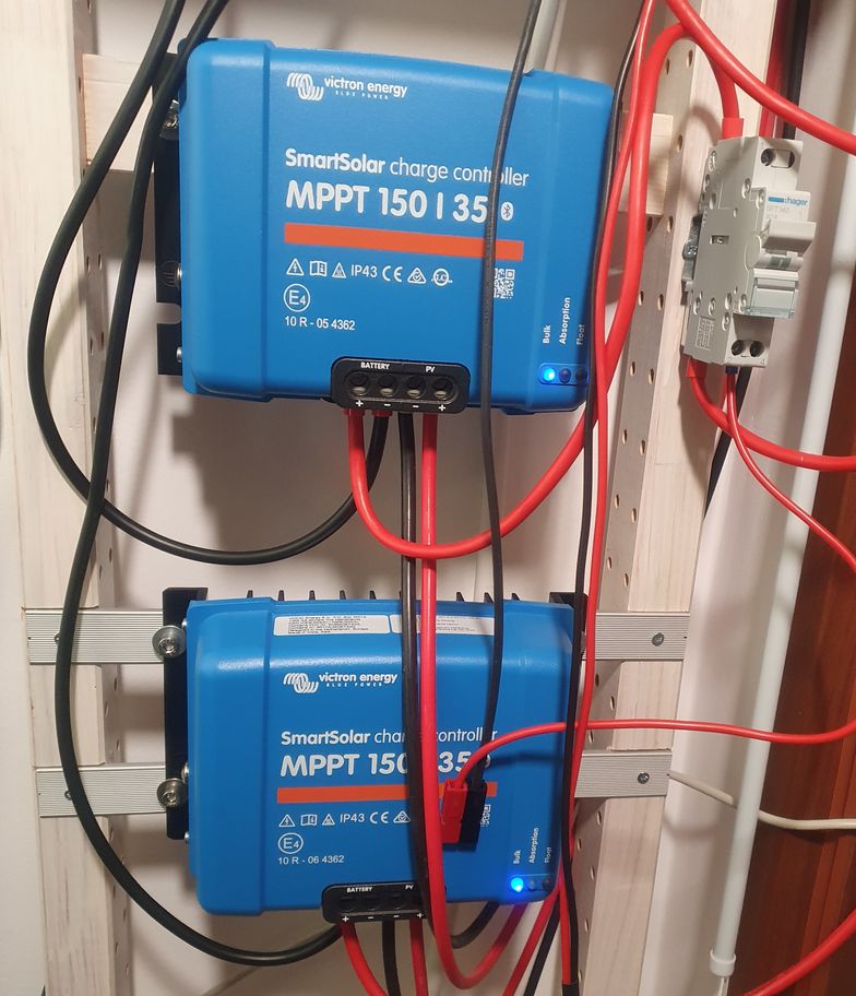
Beware: an AC switch should not be used in a DC system (arcing!) but if you make sure there is no load (use the Victron app to stop the charger first) you will be fine.
I crimped the other output with a Powerpole (andersonpower.com) connector pair and use it to charge the Kawasaki Z e-1 power packs directly (after adjusting the output voltage, of course).
Shunt / coulomb counter
As a final touch I bought the Victron 300A SmartShunt to be able to monitor battery charge (remaining capacity) and imbalance (midpoint voltage).
The SmartShunt vs BMV-712 Battery Monitor reasoning for:
- half price
- 300V/50mA SmartShunt comes with M8 terminals, everything else including BMV-712 uses M10; I don't need to recrimp my connectors with different lugs
- more voltage drop could mean more accuracy (wishful thinking).
And the drawbacks:
- doesn't have a screen
- doesn't have the programmable relay (could use it to switch the inverter on/off)
- 300V/50mA vs 500V/50mA means more voltage drop, more losses.
Home server
I use generic PC hardware optimized for low power consumption (last major upgrade in 2022):
- Fujitsu D3644-B mainboard
- i3-9100T CPU
- single stick of 32GB Crucial CT32G4DFD832A DDR4 RAM (unbuffered, non-ECC)
- 2x NVME SSDs for system/whatever (Samsung SSD 970 EVO Plus 2TB + 512GB Intel)
- 2x 12TB WDC WD120EDAZ shucked magnetic SATA drives for storage (these are spun up only when needed).
All of this is powered by a picoPSU-160-XT and an OpenUPS supported by a small 12V LifePO4 battery.
The OpenUPS works fine in both a 12V and 24V system with variable voltage but:
- there is no true shutdown signalling, there is some monitoring but powering down is implemented as a power button push
- when my battery runs flat it will never recharge - the BMS keeps the power disconnected and OpenUPS can't cope with this
- I experienced power drops and random reboots on power returns
- the configuration software will hapily accept parameters leading to unit self-destruction (did that!).
I'm on a hunt for an alternative.
The system now seems to average at about 7.5W/21W with the drives idling / in operation. The power consuption was higher at 12V, OpenUPS power conversion seems to be more efficient with higher input voltage.
The PoE stuff
The Mean Well DDR-120B-48 DC/DC power supply feeds my NETGEAR GS316EP PoE switch.
I adjusted the output voltage to 54V to match the original power brick output level.
I power multiple devices from PoE, including the Nokia G-010G-Q ONT and WiFI (GL-MT1300 Beryl) with the help of cheap PoE Gigabit power converters.
My baseline power consumption is around 21.6W at 54V. About 25.5W is pulled from the battery at 24V resulting in a ~85% conversion efficiency for the 24V to 54V step-up. The DDR-120B-48 no-load consumption is about 70mA.
DC power to the desk (tm)
I use a 4x 4mm2 installation cable and a speakON (neutrik.com) socket to terminate the power at my working desk. These are not intended to transmit power but as long as you don't confuse your connections these are excellent.
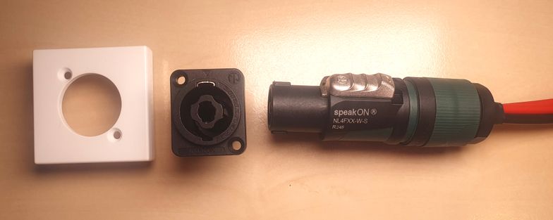
The so-called chassis connector has a typical XLR layout - I found a base plate matching my Legrand DLP conduit / cable management system (legrand.com) for a clean look. It's a K122/9 XLR plate for Simon Connect K45 series. (simonelectric.com).
These provide two separate circuits, I fused each with a 20A fuse.
Lenovo laptops/docks on USB-C PD made easy
I've been using various cigarette lighter socket-style USB-PD chargers but none of them could do 135W @20V needed to properly power my Lenovo X1 Extreme Gen3 laptop. Many will not even provide a constant 100W for long and fall back to 60W/3A operation to prevent overheating.
After upgrading the system to 24V I can now take adavantage of the YZXStudio ZC925 (youtube.com) dual USB-C PD power adapter.
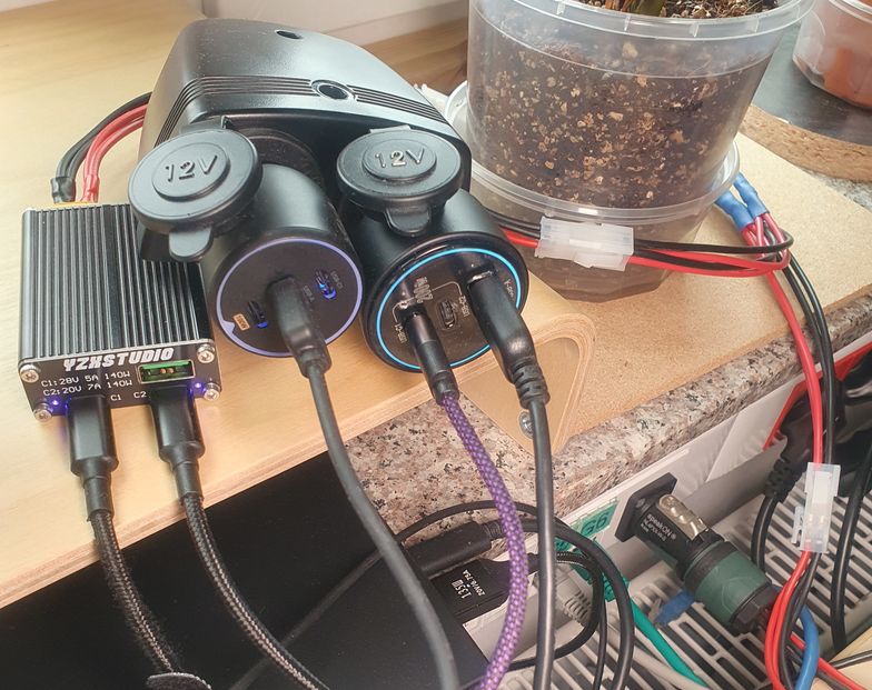
It provides two ports: one will step-up/down up to 28V 5A (PD 3.1) and the more interesing one will do 20V 7A but only step-down (buck). As of today I have no knowledge of an off-the-shelf USB-PD charger that would do 20V 7A from 12V.
There is also a ZC858 YZXSTUDIO 140W PD Fast Charge Converter (youtube.com) that provides only the 20V 7A step-down output.
I prefer the former because it accepts power through an XT60 connector (beside barrel jack and USB-C PD 20V 5A maximum). The latter only has the barrel jack.
The "lesser" C1 port capable of 100W 5A@20V powers the docking station (Lenovo USB-C Gen2 Dock). The C2 135W 7A@20V goes directly to the laptop that now runs with full sustained performance. You need the USB-C to slim tip 135W cable variant with 1kΩ resistance between the ceneter pin and ground. (thinkwiki.org)
The cigarette lighter USB-PD chargers power all the other stuff as needed.
DC display/monitor options
The easiest path to a DC-powered external display is to buy the super cheap Samsung S3 (S30GD) Essential Monitor, powered by an external power brick (14V nominal). I poked it around and it works correctly with voltages as low as 10V and as high as 15.5V (didn't push it further). There is obviously a DC-DC conversion going on - whatever the voltage, the power consumption stays almost the same. This monitor with conservative brightness consumes a little shy of 6W, not bad! The exact model I inspected is the LS24D300GAUXEN 24 FHD from 2025.
There is also a 27-inch variant and there were different iterations throughout the years, I suspect these are similar but you should check.
In a 12V system (10-14.6V) this monitor can be powered directly. That's how I use one in my overlander. In a 24V system you can use cheap USB-PD triggers that will output a standard 15V, no need to build/buy expensive PPS triggers to get exactly 14V.
These monitors only provide FHD resolutions (1920x1080). I typically use WUXGA (1920x1200) so I am planning to try to modify a Dell U2415 WUXGA to take USB-PD power, these seem to have separate AC/DC power boards internally.
AC Inverter
In my setup an inverter is an optional accessory to consume power surpluses during the summer. Around winter due to low production and massive inverter losses I consume my power exclusively as DC. My initial setup didn't include an inverter at all.
Seems I finally found the inverter I want: ECTIVE TSI 30 3000W/24V. (ective.de) It's supposed to consume only about 0.6A idle (~15W, not bad for a 3000W-capable unit, my 12V Mean Well TS-1500 idles at 35.5W!). There is also an AC bypass for power redundancy that can prioritize battery usage. You also don't need to pay for AC/MPPT chargers you don't want or need.
Still, I don't expect any inverter usage close to winter time. A single panel was only able to power my server during the worst months (~10-15W load). I expect 4 times the capacity to cover my PoE usage (~30W) plus maybe some of my desktop needs. :-)
UPS operation
At 24V when the power supplies kick-in there is still about 10% capacity left in the batteries. In worst case when an AC power failure catches me at this level there is still some runtime left. In case of two times 2.56kWh that would be about 0.5kWh so two and a half hours for a 200W load. Not a bad UPS runtime, not bad indeed. Need to verify this though.
Monitoring

I migrated my scripts to use victron-ble (github.com) exclusively. Lost PV voltage measurements as a result (not reported in the immediate readouds) but simplified the setup. With the SmartShunt I finally have precise info about battery state. I adjusted the percentage 10x to have it ploted together with the power measurements (i.e. 100% is 1000W). Looks pleasing to me.
Build parts summary
- PV panels: 4x JA Solar JAM60S20-385/MR (385W)
- chargers: 2x Victron SmartSolar MPPT 150/35
- batteries: 2x LiTime 200Ah Plus (200A max charge/discharge)
- power supplies: 2x Mean Well GST-220A24-R7B
- battery monitor: Victron SmartShunt 300A
- installation enclosure: ELEGANT RN 3X12 MULTIMEDIA IP40 part number 2445-21
- fuse boxes for ATO/ATC: 2x typical China-sourced boxes for 6 fuses and separate ground section
- fuse box mounted on battery terminal: MTA 0300468, 2x 40A MIDIVAL fuses for each of the chargers, 125A fuse for the inverter
- fuse holder battery-ATO/ATC fuse boxes: MTA 0300360, MIDIVAL 40A fuse
- 24/48V DC/DC converter (for PoE switch): Mean Well DDR-120B-48 (output adjusted to 54V)
- PoE switch: NETGEAR GS316EP
- DC/AC inverter:
Mean Well NTU-1700-224EUECTIVE TSI 30 3000W/24V (ective.de) - wiring: between batteries, battery-shunt: 50mm2 (0 AWG)
- wiring: DC/AC inverter: 25mm2 (4 or 2 AWG)
- wiring: shunt-fuse boxes ground, grounds between fuse boxes: 16mm2 (6 AWG)
- wiring: chargers: 10mm2 (8 AWG)
- wiring: solar panels-chargers: 6mm2 solar wire (10 AWG)
- wiring: battery-fuse box: 6mm2 (10 AWG)
- wiring: to DC-powered stuff: 4mm2 (12 AWG)
- wiring: cigarette lighters: 2.5mm2 (14 AWG).
TODO
- check battery reserve capacity at 24V
- modify the Dell U2410 monitor to take USB-PD power
- find or develop an OpenUPS alternative.